Theft Deterrent System
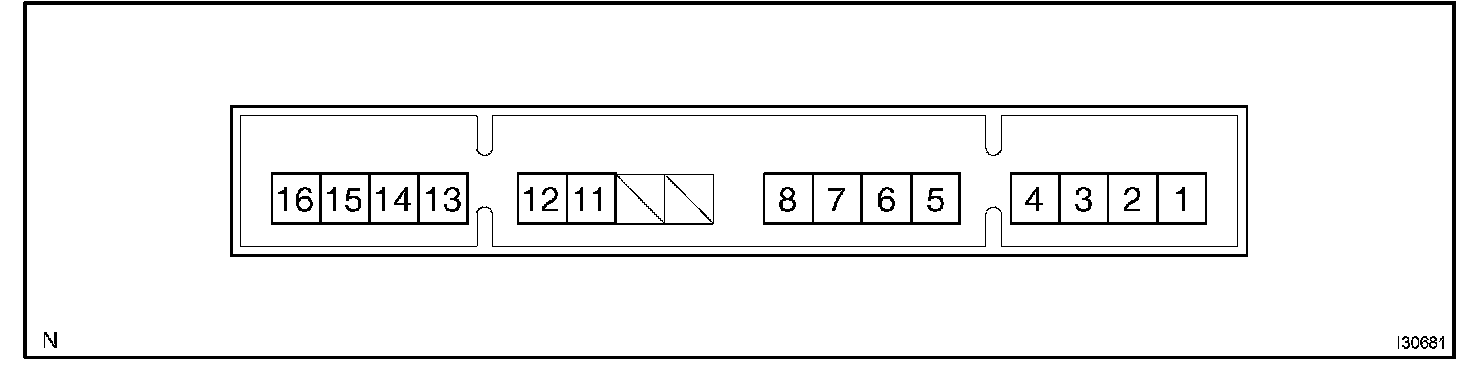
TERMINALS OF ECUTerminals Of Control Module/Pinouts (Part 1):
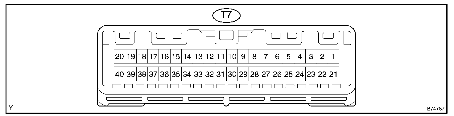
1. CHECK THEFT WARNING ECU ASSY
Terminals Of Control Module/Pinouts (Part 2):
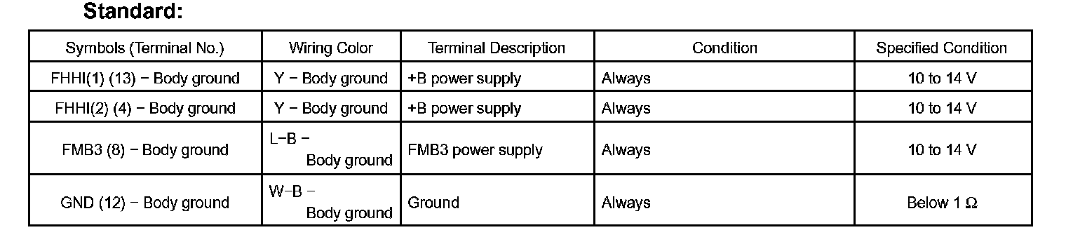
a. Disconnect the T7 ECU connector.
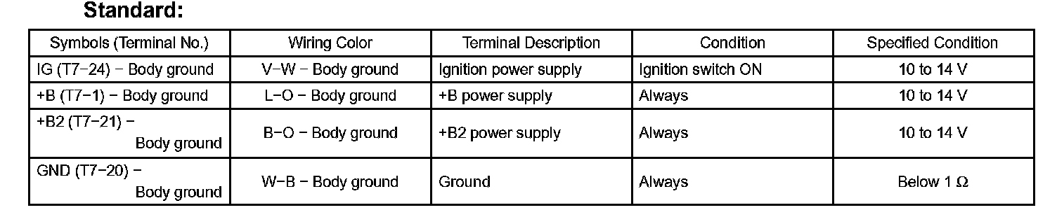
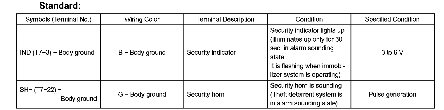
b. Measure the voltage and resistance of the wire harness side connector.
If the result is not as specified, there may be a malfunction on the wire harness side.
Terminals Of Control Module/Pinouts (Part 3):
c. Reconnect the T7 ECU connector.
d. Measure the voltage of the connector.
If the result is not as specified, the ECU may have a malfunction.
Terminals Of Control Module/Pinouts:
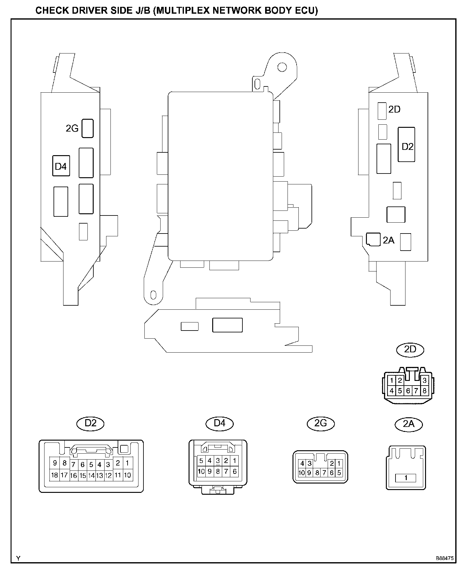
2. CHECK DRIVER SIDE J/B (MULTIPLEX NETWORK BODY ECU)
Terminals Of Control Module/Pinouts (Part 5):
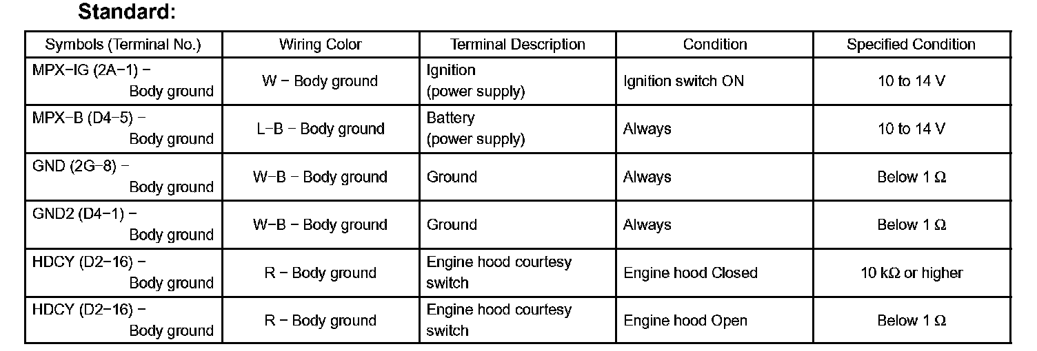
a. Disconnect the 2A and 2G J/B connectors.
b. Disconnect the D2 and D4 ECU connectors.
c. Measure the resistance and voltage of the wire harness side connectors.
If the result is not as specified, there may be a malfunction on the wire harness side.
Terminals Of Control Module/Pinouts (Part 6):
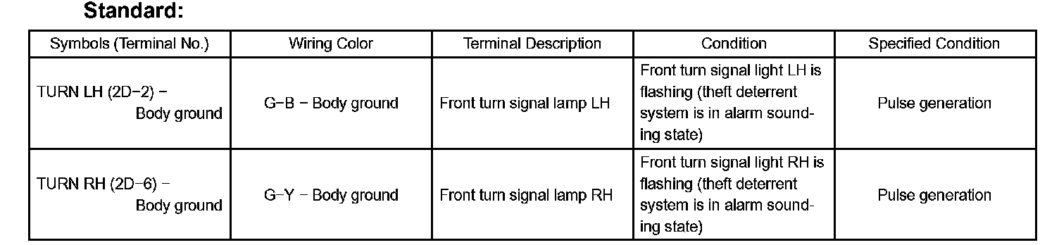
d. Reconnect the 2A and 2G J/B connectors.
e. Reconnect the D2 and D4 ECU connectors.
f. Measure the voltage of the connector.
If the result is not as specified, the ECU may have a malfunction.
Terminals Of Control Module/Pinouts:
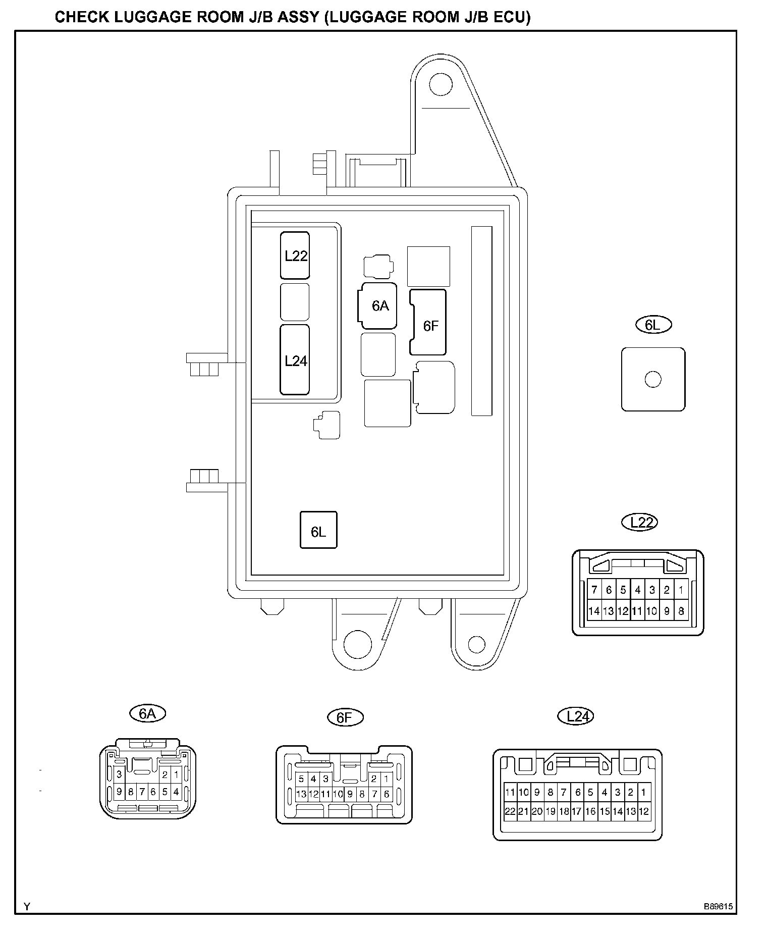
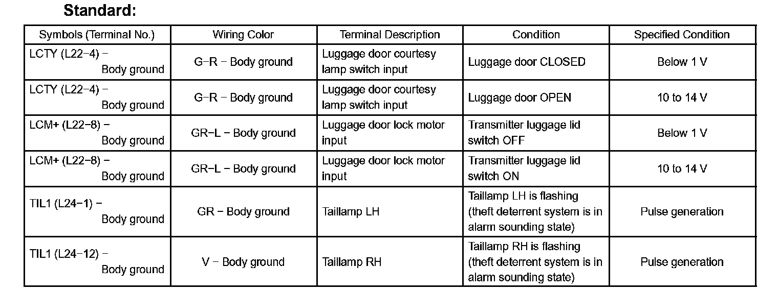
3. CHECK LUGGAGE ROOM J/B ASSY (LUGGAGE ROOM J/B ECU)
Terminals Of Control Module/Pinouts (Part 8):
a. Disconnect the 6A, 6F and 6L J/B connectors.
b. Disconnect the L24 ECU connector.
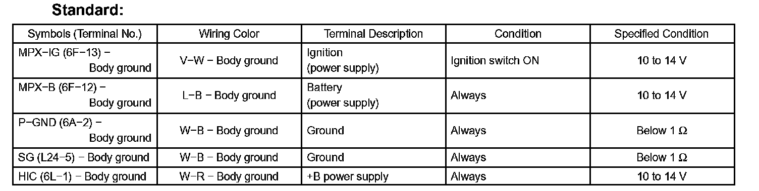
c. Measure the resistance and voltage of the wire harness side connectors.
If the result is not as specified, there may be a malfunction on the wire harness side.
Terminals Of Control Module/Pinouts (Part 9):
d. Reconnect the 6A, 6F and 6L J/B connectors.
e. Reconnect the L24 ECU connector.
f. Measure the voltage of the connector.
If the result is not as specified, the ECU may have a malfunction.
Terminals Of Control Module/Pinouts (Part 10):
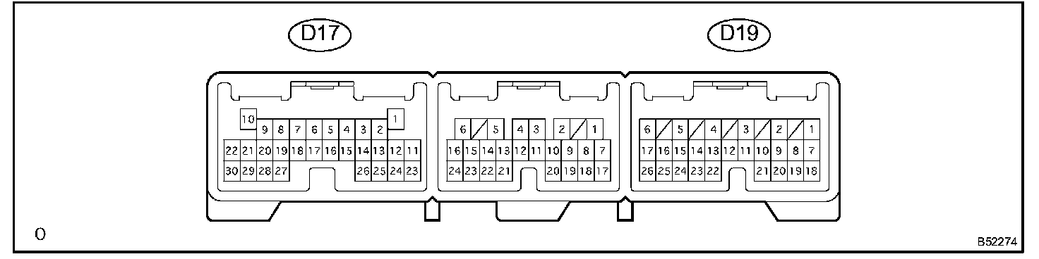
4. CHECK MULTIPLEX NETWORK DOOR ECU FRONT LH (DRIVER DOOR ECU)
Terminals Of Control Module/Pinouts (Part 11):
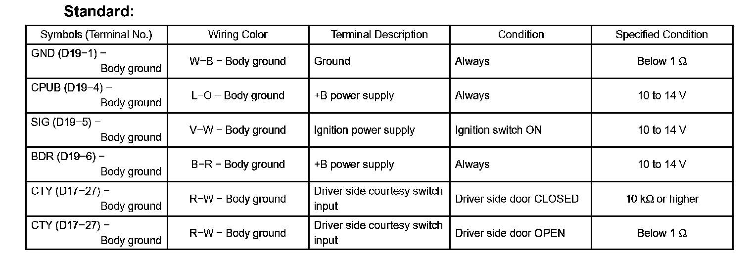
a. Disconnect the D17 and D19 ECU connectors.
b. Measure the voltage and resistance of the wire harness side connectors.
If the result is not as specified, there may be a malfunction on the wire harness side.
Terminals Of Control Module/Pinouts (Part 12):
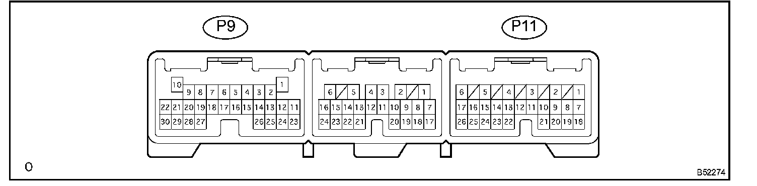
5. CHECK MULTIPLEX NETWORK BODY ECU FRONT RH (PASSENGER DOOR ECU)
Terminals Of Control Module/Pinouts (Part 13):
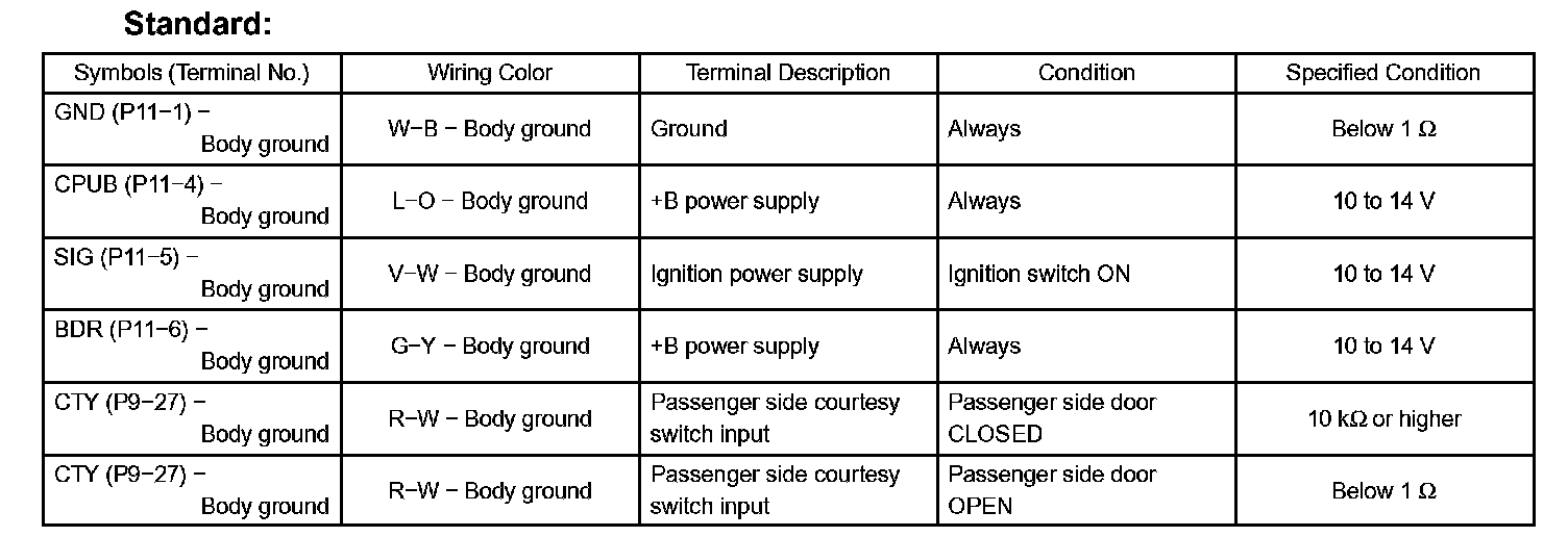
a. Disconnect the P9 and P11 ECU connectors.
b. Measure the voltage and resistance of the wire harness side connectors.
If the result is not as specified, there may be a malfunction on the wire harness side.
Terminals Of Control Module/Pinouts (Part 14):
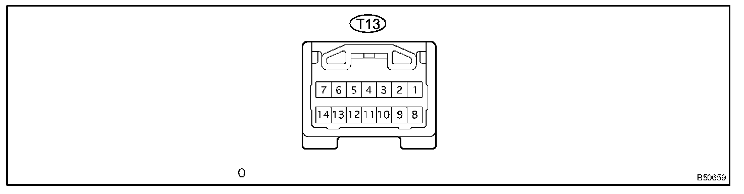
6. CHECK TRANSPONDER KEY ECU ASSY
Terminals Of Control Module/Pinouts (Part 15):
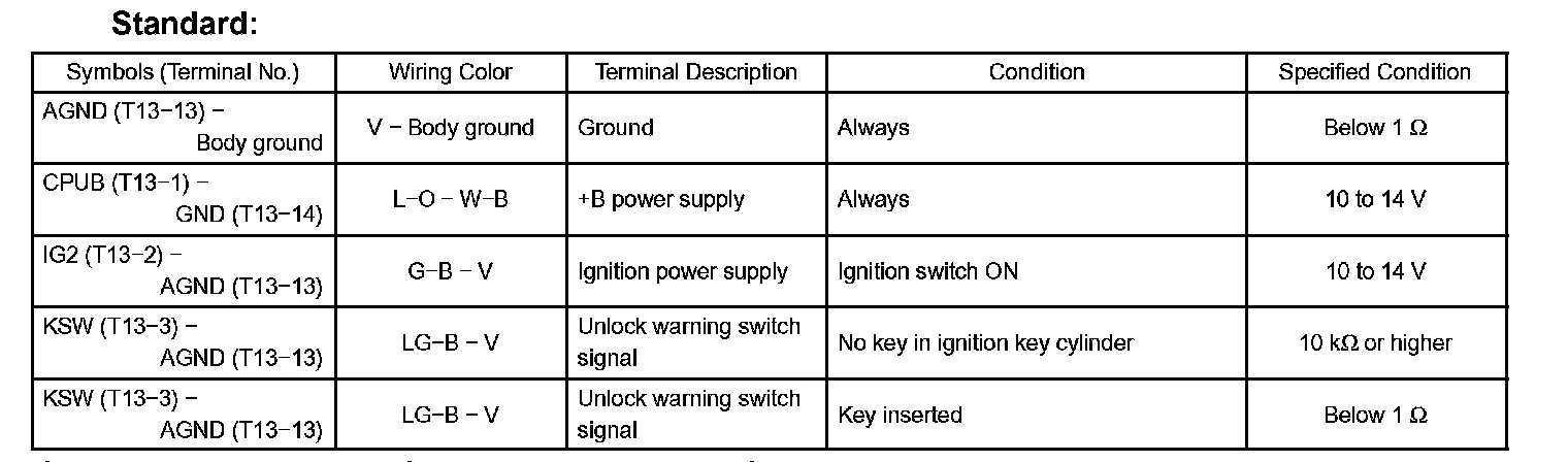
a. Disconnect the T13 ECU connector.
b. Measure the voltage and resistance of the wire harness side connector.
If the result is not as specified, there may be a malfunction on the wire harness side.
Terminals Of Control Module/Pinouts (Part 16):
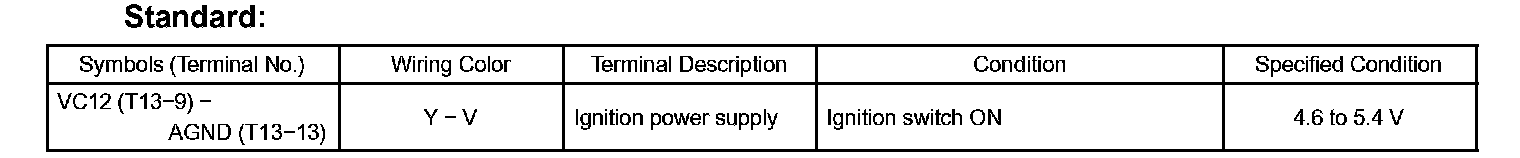
c. Reconnect the T13 ECU connector.
d. Measure the voltage of the connector.
If the result is not as specified, the ECU may have a malfunction.
Terminals Of Control Module/Pinouts (Part 17):
7. CHECK MULTIPLEX NETWORK FRONT LAMP ECU (FRONT CONTROLLER)
Terminals Of Control Module/Pinouts (Part 18):
a. Measure the resistance and voltage of the ECU.
If the result is not as specified, the ECU may have a malfunction.